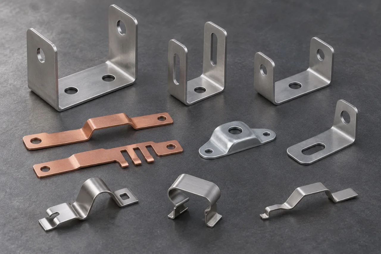
Metal stamping
Custom clips, contacts, brackets, and formed components for repeat production. Review material thickness and temper, functional edges, forming requirements, and release quantities against the approved drawing.
Explore the process
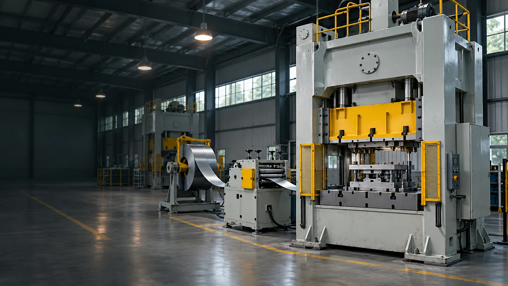
Custom stamped parts and stamping dies for OEM production. From drawing review and tool trials to inspection and repeat supply, we help define the complete manufacturing requirement.
Start with your part
WenXinDa focuses on metal stamping and stamping die tooling. Connect the part specification with the tool plan, sample approval, and requirements for repeat orders.
Custom clips, contacts, brackets, and formed components for repeat production. Review material thickness and temper, functional edges, forming requirements, and release quantities against the approved drawing.
Explore the process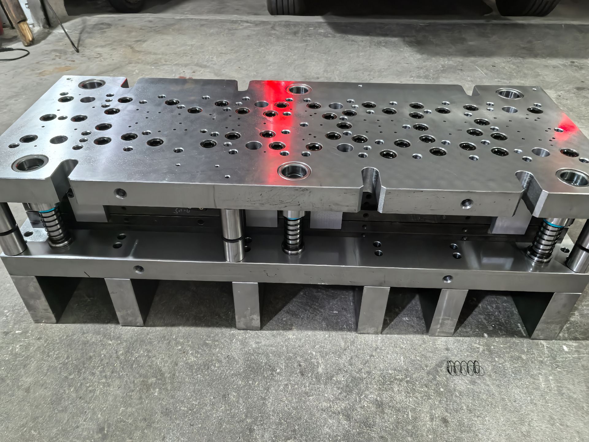
Connect the part drawing with the die concept, tool scope, trials, and sample approval. Agree ownership, maintenance responsibilities, wear parts, and future changes before the tool order.
Explore the processA die is a project in its own right. Define what the tool must produce, how trials will be approved, and what is included in the handover.
Review the material, forming sequence, critical geometry, and expected releases. Confirm whether the order covers tooling, stamped parts, or both.
Agree the trial material, sample quantity, dimensional report, and functional checks. Resolve adjustments before the production reference is approved.
Define tool identification, ownership, storage or shipment, receiving press interfaces, and the documents included with the tool.
Agree responsibilities for upkeep, wear parts, repairs, and later drawing changes. Define how changes are reviewed and reapproved.
Sheet metal fabrication supports cut, bent, and assembled features. CNC machining supports tooling components, secondary features, and related machined parts. Include the required scope with your drawing.
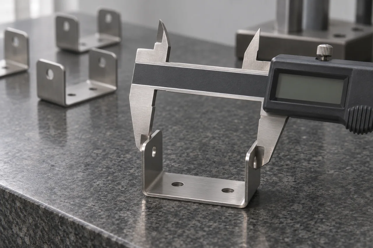
Stamped parts need a shared reference for material, formed features, edges, and finish. Connect the approved drawing and trial samples with the inspection plan before production release.
A bracket that fits. A contact that meets its mating interface. A die built around the receiving press. Explore the decisions behind six common OEM project briefs, then bring us the details of your own part.
Industrial equipment / formed brackets
A formed mounting bracket connects functional datums, hole position, bend geometry and final coating in one approval plan. Explore the manufacturing route, sample checks and repeat-order requirements that help OEM purchasing move a controlled component into planned industrial equipment assembly.
A mounting bracket can look right on the bench and still hold up the assembly line. Hole position, bend angle and coating thickness all affect how it seats against the mating component. The project starts by identifying the mounting faces and the dimensions that control the fit, rather than treating every drawing dimension as equally important.
The objective is a bracket the receiving team can identify, inspect and move into assembly with a clear approval record. Send the mating details with your drawing to make the quotation more useful.
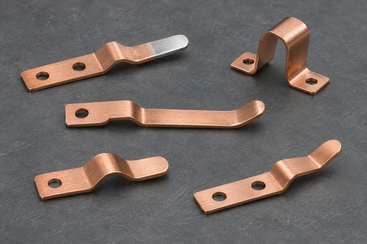
Electrical assemblies / clips & contacts
A copper-alloy contact brings material temper, working deflection and plated surfaces into a single manufacturing brief. Follow the design review, forming route, functional approval and repeat-order controls that connect a stamped component to its electrical assembly and agreed delivery requirements.
A spring clip or electrical contact has to do more than match an outline. Its working shape, material temper and contact surface affect the assembly. A useful project brief defines the installed position, mating interface and required checks before tooling decisions are locked in. Small details around bends and edges deserve attention early.
The objective is a repeatable part specification that connects the drawing to the way the component works. Include the mating part or a section view so the review can focus on the interface that matters.
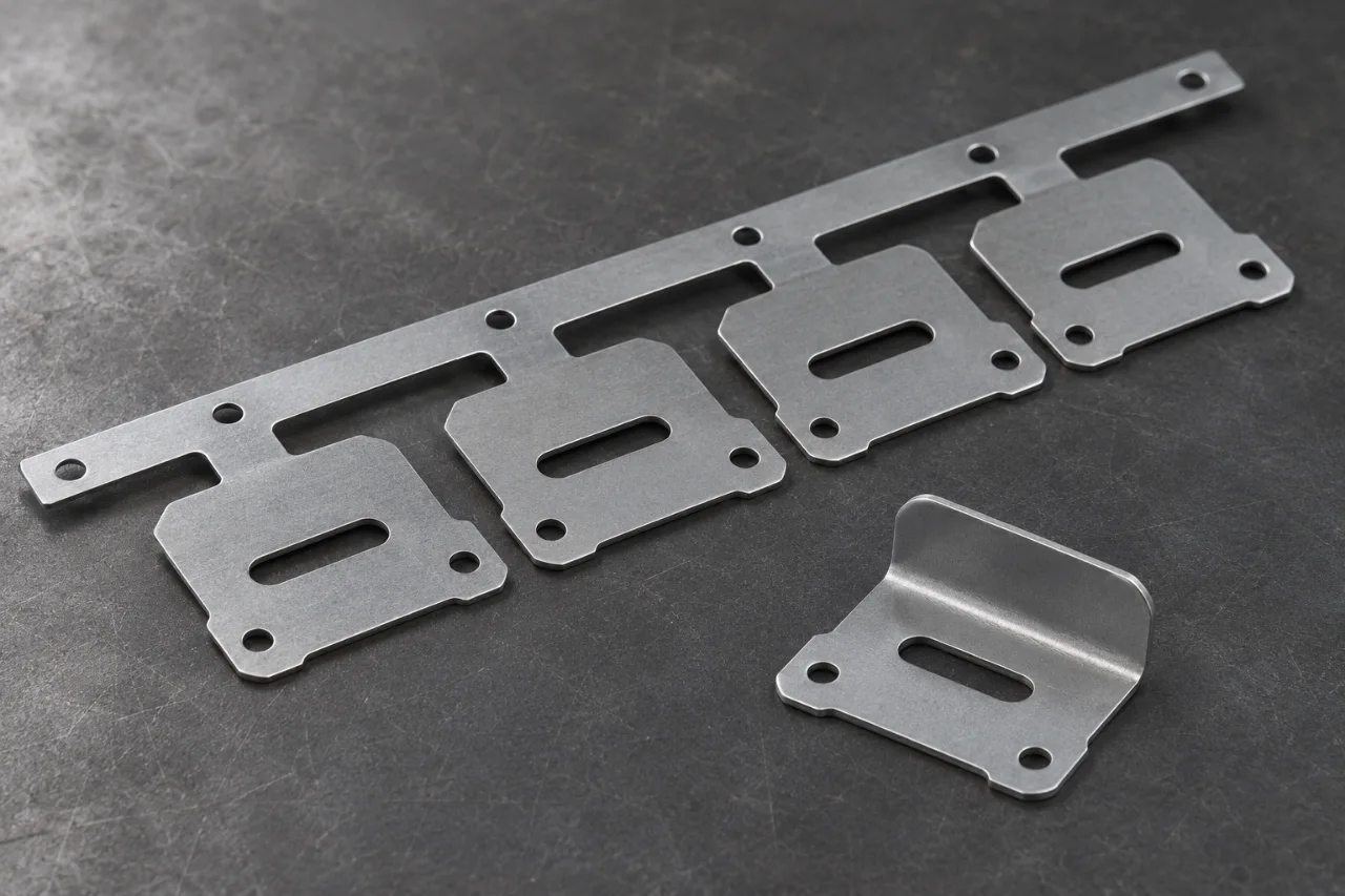
OEM production / progressive die development
A recurring formed part needs a route comparison that includes tooling, material use, finishing and approval. Review cutting and bending alongside progressive die production, using design stability, forecast releases and complete program cost to guide the next informed sourcing decision.
A formed part with repeated releases needs a tooling decision that accounts for more than the quoted piece price. Strip layout, material yield, trial work and tool care all belong in the program. The brief connects the current drawing to the expected release pattern, so the first tool is planned for the work that follows.
The objective is a clear route from tool investment to an approved production part. Send both the first release quantity and the repeat forecast to compare the manufacturing options on the same basis.
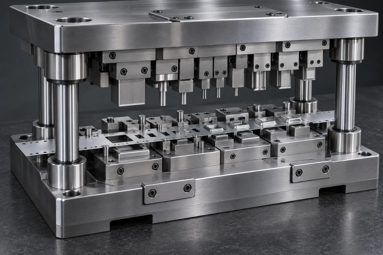
Tooling procurement / press-ready handover
A die-only purchase connects the component drawing with the receiving press, feeding arrangement and handover scope. Explore mechanical interfaces, ownership, trials, sample approval and transfer documents that help purchasing define a complete tool supply package for its intended production setup.
A die-only purchase needs to work at the receiving facility. Press interfaces, material feeding and handling arrangements influence the design from the beginning. This project brief makes the destination press part of the specification, alongside the finished part, so installation and handover requirements are addressed before the tool is built.
The objective is a tool purchase with clear installation inputs and an orderly approval path. Include the press data and handover checklist with the part drawing to start a focused tooling review.
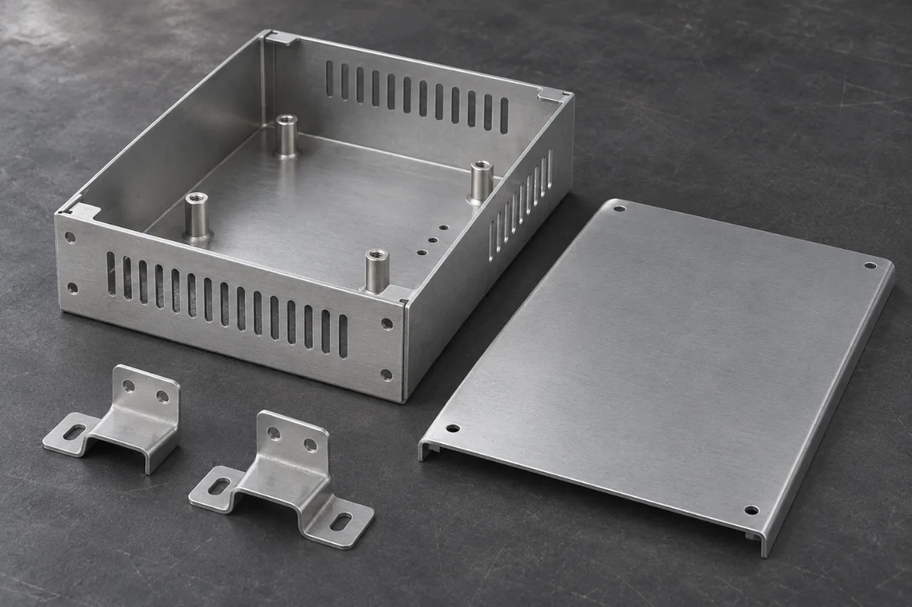
Equipment housings / supporting sheet metal
A sheet metal equipment enclosure brings cut panels, bend relationships, joints, hardware, coating, and cover fit into one assembly. The brief connects drawings with the finished housing, a controlled approval record, an organized quotation, and protective delivery for repeat purchasing.
An equipment enclosure brings cut profiles, bends, hardware and surface finish into one assembly. A panel may pass its individual checks while access holes, mounting points or doors fail to line up after finishing. The project review follows the complete assembly and the receiving requirements, rather than quoting disconnected flat parts.
The objective is an enclosure package that is straightforward to receive and build into the equipment. Send the assembly model as well as individual drawings to make the fabrication scope easier to evaluate.
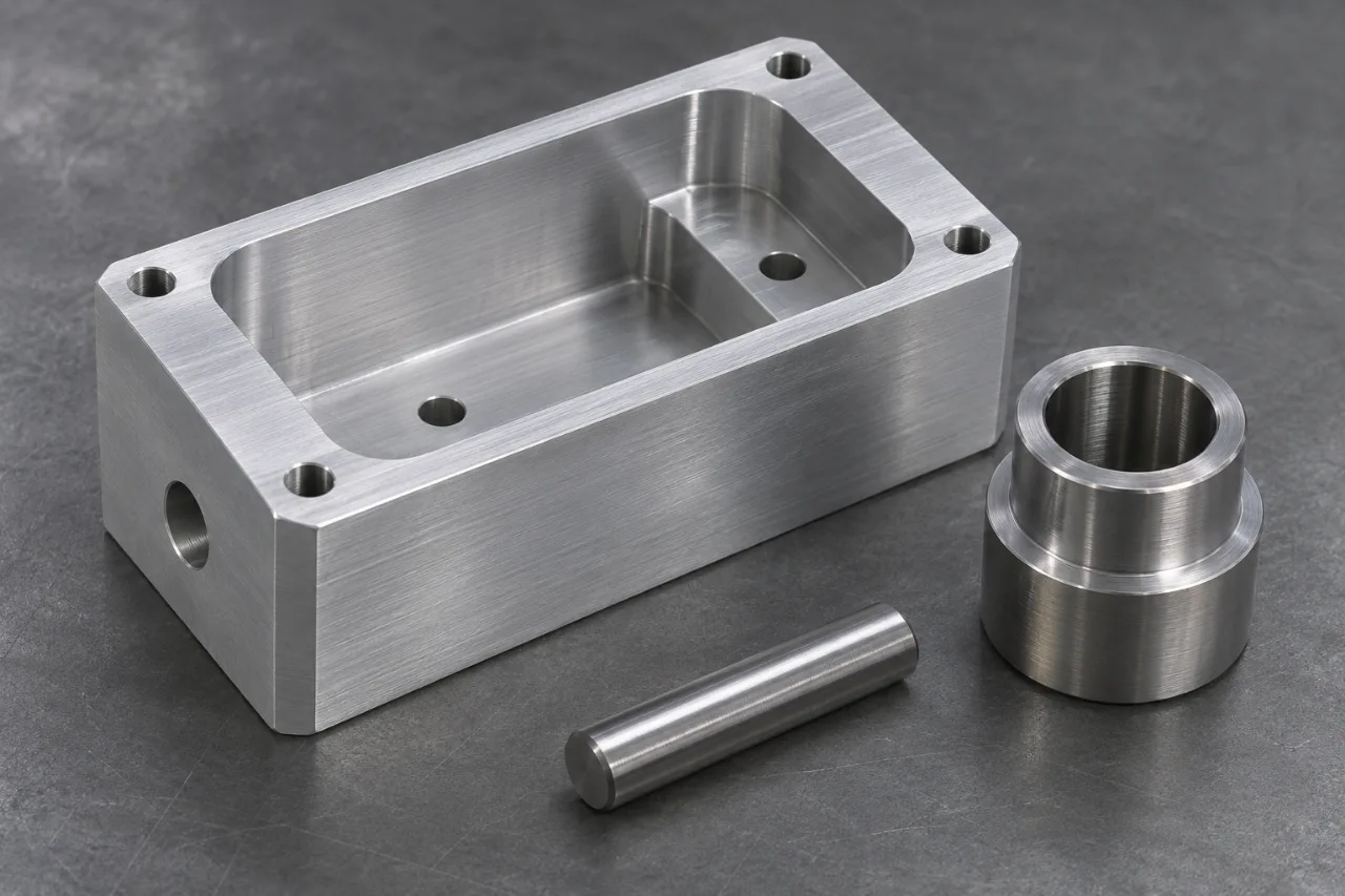
Tooling & equipment / supporting CNC parts
CNC locating components connect mounting faces, pin holes, bores, shoulders, and threads through a functional datum scheme. The brief brings material, workholding, machining access, treatment, final fit, inspection records, and protected packing into a defined interface for tooling or equipment.
A machined locating block, fixture component or mounting interface often carries the dimensions that connect several parts. A tight tolerance has value when it protects the intended fit. The review starts with the locating scheme, access for machining and the final inspection condition, connecting the part drawing to the assembly task.
The objective is a supporting component with a clear fit requirement and a proportionate inspection plan. Mark the mating features when you request a quote so the review targets the dimensions that do the work.
Send the drawing you have today. Add the material, order quantities, and the feature that is causing the most discussion. Tell us whether your priority is assembly fit, tooling scope, unit cost, or repeat supply. We can focus the project review on the decision your team needs to make next.
Thickness, temper, grain direction, and surface treatment influence forming as well as finished function. Include the material condition with the grade when comparing stamping options.
| Material family | Design considerations | Include in the RFQ |
|---|---|---|
| Aluminum alloys | Thickness, temper, bend behavior and surface appearance | Grade, thickness, temper, cosmetic faces and finish |
| Stainless steels | Corrosion environment, forming behavior and springback | Grade, thickness, condition and surface treatment |
| Carbon & alloy steels | Formability, strength, heat treatment and corrosion protection | Grade, thickness, condition and coating specification |
| Brass & copper alloys | Conductivity, contact behavior, forming and surface protection | Alloy, temper and any plating requirements |
Choosing between materials? Tell us about the operating environment and the feature that matters most.
A useful quote lets you see what you are buying. We bring the part, tooling, finish, inspection, and delivery requirements together, so your team can compare the complete order and plan the next stage.
You can start before every detail is fixed. Send the current design and tell us which material, finish, or quantity options you would like to compare.
See the process and cost comparison
One project, four clear stages. Your drawing, quotation, approval, and delivery requirements stay connected as the order moves forward.
Send the current drawing and CAD, grade, thickness, temper, first batch quantity, and repeat forecast. Highlight functional bends, edges, finish, and delivery needs.
Review the die approach and supply scope. Separate one-time tooling and trial charges from repeat part cost, and agree ownership, maintenance, finish, and inspection.
Check trial parts against the drawing, critical formed features, edge requirements, and assembly. Record adjustments and establish the approved sample and revision before production.
Protect finished surfaces, identify each part, and organize the documents needed at receipt. Packing and freight are planned around the destination and delivery terms.
Whether you are testing a design, moving an existing part, or ordering another batch, we focus the work on the outcome your team needs.
Review the forming features and tool approach while the design develops. Separate early fit checks from production-intent trial parts, and agree the approval steps before committing to a die.
Explore the processesShare the approved drawing, tool information, reference samples, and inspection criteria. For a proposed tool transfer, compatibility, condition, ownership, and trial responsibilities need a separate review.
Plan acceptanceBuild repeat orders around the approved part number, revision, and release size. A demand forecast helps align tooling, material purchasing, packaging, and the schedule for future batches.
Discuss a repeat program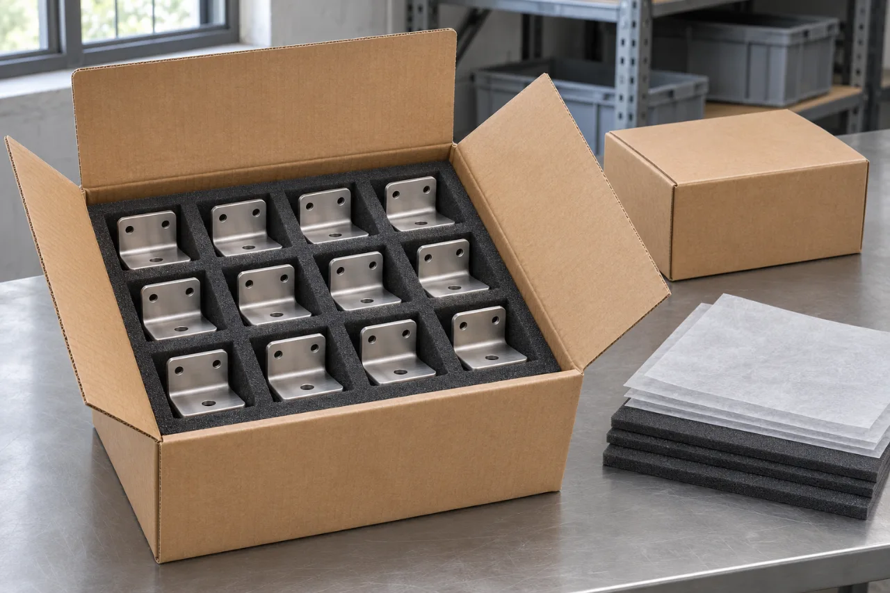
Edges, coatings, and packing deserve the same attention as dimensions. Deburring improves handling; masking protects threads and fits; separators help finished surfaces arrive in good condition. These details form part of a complete manufacturing order.
We work through the finishing and delivery details alongside the part specification, giving purchasing and receiving teams a clear reference for the order.
Explore packing and shippingIdentify critical features, sample approval, measurement method, and the reports needed with delivered parts.
Read the guideLearn how datums, fits, edge conditions, visible faces, and coatings should be communicated on a drawing.
Read the guidePlan protective packing, labels, shipping documents, trade terms, and the named receiving point before dispatch.
Read the guideShow us the mounting face, contact surface, or mating part. We focus the review on the dimensions and formed features that make your component work in the assembly.
Review your part requirementsCompare die development, trial work, repeat part prices, finish, inspection, and packing on the same basis. Give purchasing a scope they can evaluate and engineering a route they can approve.
Compare manufacturing routesConnect the approved revision to material condition, repeat releases, tool care, and receiving checks. Make the production reference useful for the orders that come next.
Plan a repeat production partSend the current CAD or drawing, material, quantity, and delivery destination. Add the finish and any critical dimensions. If you want options, include the first batch quantity and your expected repeat demand.
Yes. State whether you need a new stamping die, stamped parts, or a tooling-and-production project. For a die-only enquiry, include receiving press interfaces and handover requirements so compatibility and the scope can be reviewed.
Mark the critical dimensions and include your inspection template if you have one. We work with the drawing, sampling requirements, and report format so the inspection scope is clear with the quotation.
Use the contact form for up to 3 files, 10 MB each, or send the package to the sales email on our contact page. Include the part number and revision. If your project needs an NDA, mention it before sending the design files.
Ask for die development, trials, and repeat part pricing to be shown separately. Ownership, maintenance, wear parts, storage, and later revisions should be agreed with the quotation. The economics depend on the part and release pattern.
Consider it when a sheet part has a stable drawing and a repeat order pattern that may justify dedicated tooling. Compare tool cost, expected releases, sample approval, tool ownership, maintenance, and change control with a fabrication route.
CNC is a supporting capability for tooling components, secondary features, or related machined parts. Add the required operation and mating features to the enquiry so the supply scope and inspection can be reviewed together.
Compare the same drawing revision and quantities, then check what each quote includes: material, one-time tooling, part operations, finish, inspection records, packing, freight, and delivery term. A unit price alone does not describe the full purchase scope.
Get the part, tool, trial samples, and repeat-order scope into one conversation. Send your current drawing, material, and quantities. Let’s work through the next decision.